
Summary of Contents for Vivint Go!Control
-
Page 1: User Guide
USER GUIDE Go!Control WIRELESS SECURITY SYSTEM WARNING: Owner’s Instruction Notice Not to be removed by anyone except occupant... - Page 2 The Go!Control Security System Congratulations on your ownership of a Go!Control Security System! This wireless system offers protection for your property against burglary, protection for yourself and family with 24-hour emergency monitoring, and optionally fi re detection for your home.
-
Page 3: Table Of Contents
Table of Contents System Overview Test Mode Icon ..............2 General Information . -
Page 4: System Overview
System Overview General Information This system provides three forms of protection: burglary, fi re, and emergency, depending on the options set by the installer. The system consists of the Control Panel with a color touch screen, wireless sensors that provide perimeter and interior burglary protection, and wireless smoke and carbon monoxide detectors. -
Page 5: General Operation
System Overview General Operation Following are general operational concepts that your system supports. Understanding these concepts will help you to use your security system to it fullest extent. Sensor Types The system’s wireless sensors have been assigned to selected “types” (sometimes called “zones” in the alarm industry). -
Page 6: Control Panel Features
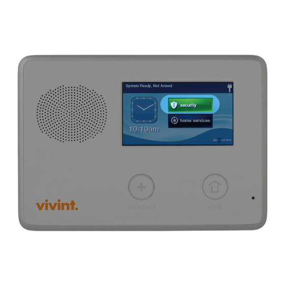
Control Panel Features ALARM SOUNDER COLOR DISPLAY AND SPEAKER WITH TOUCH SCREEN Sounds all system local alarms, Shows all system information, status, voice prompts, system sounds, and programming, and functions as the keypad audio for 2-way voice communications Display cycles clock, calendar, and weather with the Central Station (press to manually change) MICROPHONE... -
Page 7: Wireless Sensors
Wireless Sensors Your security system has wireless sensors. Some sensors will be visible, other sensors are hidden inside the door jambs. Depending on your installation, there may be other types of sensors shown below. Be sure your installer shows you all the sensors installed in your system. Door / Window Sensor Motion Sensor Glass Break Sensor... -
Page 8: Main Display Screens
Main Display Screens The Control Panel is programmed and operated using the color touch-screen display. The Silent Control display will show various buttons, indicators, and text to guide and inform you. The top bar on the display shows the current Display Off system mode, scrolling text of any pending alerts, and system status icons for AC power,... -
Page 9: Burglary Protection
Burglary Protection Operating the System When your system was setup by your installer, wireless sensors were placed to monitor specifi c doors and windows. The installer selected these doors and windows as likely places where an unlawful intrusion might occur and could be detected. Each sensor was programmed to have the system react in a specifi... -
Page 10: Sensor Status
Burglary Protection Sensor Status The security system constantly monitors all of the sensors attached to the protected doors and windows in your home or business. The Control Panel knows if each protected door or window is open or closed. The open or closed condition of the protected doors and windows is called the “sensor status”. -
Page 11: Sensor Bypassing
Burglary Protection Sensor Bypassing Before the system can be armed, all protected doors and windows must be closed or bypassed. The system uses “bypasses” to resolve open sensors on protected doors or windows before arming the system. When a sensor is bypassed, the system ignores that the door or window is open. There are two types of sensor bypasses available: forced and manual. -
Page 12: Stay Mode
Burglary Protection Stay Mode Stay Mode is for arming the system when people will be staying on the premises. Stay Mode arms the sensor-protected perimeter doors and windows while not arming the interior motion sensors or other interior doors. This allows the premises to be occupied while the system is partially armed. Stay Mode is used mostly for arming the system during the evening hours after everyone is inside and no one is expected to enter or leave. -
Page 13: Arming To Stay Mode
Burglary Protection Arming to Stay Mode Use Stay Mode to arm the system when anyone will be staying home. Stay Mode normally has an Entry Delay so someone with a User Code can re-enter without causing an alarm. 1. Close all protected perimeter doors and windows before arming. 2. -
Page 14: Away Mode
Burglary Protection Away Mode Away Mode is for arming the system when everyone will be leaving the premises. Away Mode arms all sensor-protected perimeter doors and windows, interior motion sensors, interior glass break sensors, and any other sensor-protected interior doors. The premises must be unoccupied while the system is armed. -
Page 15: Arming To Away Mode
Burglary Protection Arming to Away Mode Use the Away Mode to arm the system when everyone will be leaving the home. The Away Mode normally has an Entry Delay so someone with a User Code can re-enter without causing an alarm. Interior and perimeter sensors are armed in the Away Mode. -
Page 16: Disarming The System
Burglary Protection Disarming the System To stop the Control Panel from triggering burglary alarms, the system will need to be disarmed. Disarming turns off the burglary detection part of the system for sensors that are not 24-hour sensors. Disarming also stops any type of alarm in process. The system should be disarmed from Stay Mode before exiting the premises. -
Page 17: If A Burglary Alarm Occurs
Burglary Protection If a Burglary Alarm Occurs If an armed sensor is tripped while the system is armed in the Stay or Away Mode, an alarm will occur and the siren will sound. Delayed sensors will start the Entry Delay to allow time to disarm the system. -
Page 18: Key Fob Arming And Disarming
Burglary Protection Key Fob Arming and Disarming Your system may be equipped with one or more wireless key fobs. Up to eight key fobs can be used to control the system remotely. Each key fob has four buttons and can perform fi ve functions. A User Code is not required when arming or disarming the system with a wireless key fob. -
Page 19: Wireless Keypad Arming And Disarming
Burglary Protection Wireless Keypad Arming and Disarming Your system may be equipped with one or more wireless keypads. Up to four wireless keypads can be used to control the system remotely from the main Control Panel. Two types of wireless keypads are available. The standard wireless keypad, and the wireless touch screen keypad. -
Page 20: Fire Protection
Fire Protection Fire Alarm System Your system may be installed with smoke detectors and carbon monoxide (CO) detectors as part of an overall fi re and gas protection system. The fi re protection part of the security system is active 24 hours-a-day, offering continuous protection. -
Page 21: Recommended Smoke Detector Locations
Fire Protection This equipment should be installed in accordance with Chapter 2 of the National Fire Alarm Code, ANSI/NFPA 72, (National Fire Protection Association, Batterymarch Park, Quincy, MA 02269). Printed information describing proper installation, operation, testing, maintenance, evacuation planning, and repair service is to be provided with this equipment. -
Page 22: Emergency Evacuation Plan
Fire Protection Emergency Evacuation Plan To establish and regularly practice a plan of escape in the event of fi re, the following steps are recommended by the National Fire Protection Association: 1. Position your detector or your interior and/or exterior sounders so that they can be heard by all occupants. -
Page 23: Emergency Functions
Emergency Functions 24-Hour Emergency Buttons Three 24-hour emergency functions are available: PANIC, FIRE, and EMERGENCY. These functions can be activated by buttons on the Control Panel. The emergency functions can also be activated using wireless sensors, from the wireless keypad, or from portable pendant devices. button displays the emergency screen, it does not trigger an alarm. -
Page 24: System Trouble Alerts
System Trouble Alerts The system monitors itself for abnormal operating conditions and will alert you if trouble is detected. The system monitors these and other conditions: • AC power to the Control Panel • The telephone line (optional) • The cellular telephone connection (if used) •... -
Page 25: System Status Icons
System Status Icons The top line of the Control Panel’s display is the status area that shows the current system mode, the status of the sensors, and any current trouble alerts. Special icons are displayed to visually show the system’s current condition. Status Icon Area System Status Icons AC Power Icon... -
Page 26: Messaging
Messaging System Messages Your security system supports receiving messages from the Central Monitoring Station. The messages can be about system upgrades, additional services, special regional weather alerts, etc. The messages can be sent for all system users to read, or as confi dential messages that only the Master User can read. -
Page 27: Reading Confi Dential Messages
Messaging Reading Confi dential Messages When a confi dential message is sent to the Control Panel, only users with the Master User Code can display the message. Use the following steps for confi dential messages: 1. Press the message line on the message list. -
Page 28: Remote Control By Telephone
Remote Control by Telephone Telephone Remote The system can be controlled remotely using a standard telephone. Remote control is performed by calling the system and responding to spoken questions from the system. By pressing certain telephone keys, you can arm and disarm the system, bypass sensors, and query the system status. ✓... -
Page 29: Remote Control
Remote Control by Telephone Remote Control Once you are connected with the system, you will be able to check on its status and remotely control the major functions. The announcements that the system plays over the telephone do not sound out of the Control Panel’s speaker. -
Page 30: System Toolbox
System Toolbox User Management The system installer has pre-programmed a Master User code for your system. This code can be used to control the system, as well as assign and change the other seven User Codes. The Master User Code can also access several system setup settings in the User Toolbox. The other seven User Codes are restricted from those settings in the User Toolbox. -
Page 31: User Code Access Schedules
System Toolbox User Code Access Schedules User Codes can be setup with one or more “Access Schedules”. The schedules allow the User Code to be valid only during certain times on specifi c days of the week, a single day, or a range of days. This feature is useful for limiting access to the system via User Codes custom tailored for specifi... -
Page 32: Recurring User Access Schedule
System Toolbox Recurring User Access Schedule Up to seven Recurring User Access Schedules can be set for each User Code. 1. Select RECURRING for the schedule type. 2. Press the calendar button to view the Recurring User Access Schedule Screen. Recurring Schedule Selected 3. -
Page 33: Date Range User Access Schedule
System Toolbox Date Range User Access Schedule 1. Select DATE RANGE for the schedule type. 2. Press the calendar button to view the Date Range User Access Schedule Screen. 3. Press the fi rst day button to set Date Range Schedule Selected the month, day, and year that this User Code will fi... -
Page 34: Changing A User Code
System Toolbox Changing a User Code 1. On the User Management Screen, press the USER button for the code change. 2. Press CHANGE PIN. (The currently set PIN is displayed on the button.) 3. Enter a new four-digit code for the User Code and press OK. -
Page 35: Duress User Code
System Toolbox Duress User Code The Duress User Code (User Code #8) performs a special function. Controlling the system with this code gives the appearance of normal operation, but using it secretly sends a “duress” report to the Central Monitoring Station to initiate a silent alarm call for help. USE THIS CODE ONLY IF SOMEONE IS FORCING YOU TO OPERATE YOUR SECURITY SYSTEM AGAINST YOUR WILL. -
Page 36: System History
System Toolbox System History The Control Panel keeps a log of system events in the order in which they occur. Each event is marked with the date and time that the event occurred. To make reading the log easier, the system history display can be “fi ltered” to show selected events only. -
Page 37: System Test
System Toolbox System Test Even though your security system is self-monitoring, it is important to regularly test the system manually. The System Test is used to test each of the sensors in the system. The Master User Code is required to test the system. While the system is in test mode, a “T” icon will blink on the upper right of the display. -
Page 38: Telephone Test
System Toolbox Telephone Test Your security system may be connected to your telephone line. The system can communicate with the Central Monitoring Station over your telephone line. Your system can send its alarm messages and system trouble or status messages using the land-based telephone system. 2-way audio communications with the Central Monitoring Station can also occur through the telephone connection. -
Page 39: Cell Phone Test
System Toolbox Cell Phone Test Your security system may be equipped with a built-in cellular radio. The cellular radio communicates between your security system and the Central Monitoring Station. Your system can send its alarm messages and system trouble or status messages over-the-air without using the land-based telephone system. -
Page 40: Chime Options
System Toolbox Chime Options On doors and windows monitored by sensors, the system can sound a chime to announce that the door or window was opened. Sensors can also be set to have the Control Panel say the name of the opening. -
Page 41: Brightness / Volume
System Toolbox Brightness / Volume The brightness of the Control Panel’s display and the volume of the system’s speaker can be adjusted to best suit the installation. To set the brightness and volume, use the following steps: 1. On the Home Screen, press SECURITY. 2. -
Page 42: Display Cleaning
System Toolbox Display Cleaning There is a special option that allows the display to be cleaned. The option locks the display for 30 seconds so it can be cleaned without sensing any button presses. Clean the display with a dry, soft cloth. -
Page 43: Set Date And Time
System Toolbox Set Date and Time The Control Panel has a built-in clock and calendar. The time and date are displayed on the Home Screen. The time and date are also used for the system history and event logs that store data on system events. -
Page 44: Installer Set Options
Installer Set Options The installer can set different options for the system to customize the installation. The options listed below show the regular settings and have an area or check box to note custom settings. Siren Run Time If there is a burglary, panic (police), or emergency alarm, the Control Panel will sound the siren for a preset time. -
Page 45: 24-Hour Emergency Functions
Installer Set Options 24-Hour Emergency Functions Three 24-hour emergency functions: PANIC, FIRE, and EMERGENCY can be activated by buttons on the Control Panel. The installer can set which emergency buttons on the Control Panel are active. ACTIVE CONTROL PANEL EMERGENCY BUTTONS ❑... -
Page 46: Key Fob Arm/Disarm Sound
Installer Set Options Key Fob Arm/Disarm Sound The system can be set so when it’s armed or disarmed by a wireless key fob, a beep will sound through the internal and external sounders to indicate that the key fob’s signal was received. This helps in installations where the Control Panel is not visible or there are no other system status indications at the key fob’s location. -
Page 47: Cancel Display
Installer Set Options Cancel Display A “cancel” message will be sent to the Central Monitoring Station if the system is disarmed within a preset period of time after an alarm is triggered. The system can be set to display that a cancel report was sent, or for higher security, the system can be set not to display the cancel message. -
Page 48: Regulatory Information
Regulatory Information Wireless Product Notice Radio controls provide a reliable communications link and fi ll an important need in portable wireless signaling; however, there are some limitations which must be observed. • For U.S. installations only: The radios are required to comply with FCC Rules and Regulations as Part 15 devices. -
Page 49: Fcc Part 68 Notice
Regulatory Information FCC Part 68 Notice This equipment complies with Part 68 of the FCC rules and/or the requirements adopted by the Administrative Council for Terminal Attachments (ACTA). On the rear of this equipment is a label that contains, among other information, a telephone products identifi... -
Page 50: Industry Canada Notice (For Canadian Users)
Regulatory Information FCC Part 68 Notice (continued) Alarm dialing equipment must be able to seize the telephone line and place a call in an emergency situation. It must be able to do this even if other equipment (telephone(s), answering system, computer modem, etc.) already has the telephone line in use. To do so, alarm dialing equipment must be connected to a properly installed RJ31X that is electrically in series with and ahead of all other equipment attached to the same telephone line. -
Page 51: Service Information
Service Information Your local Alarm dealer is the person best qualifi ed to service your alarm system. Be sure to set up a routine service schedule with your local Alarm installer. THIS EQUIPMENT MUST BE CHECKED BY A QUALIFIED TECHNICIAN AT LEAST EVERY THREE YEARS. -
Page 52: Important Notice
Important Notice Alarm System Limitations This security system can not offer guaranteed protection against burglary, fi re, or other emergencies. Any alarm system, whether commercial or residential, is subject to compromise or failure to warn for a variety of reasons. For example: •... -
Page 53: Limited Warranty
Limited Warranty This product is warranted against defects in material and workmanship for twelve (12) months. This warranty extends only to wholesale customers who buy through authorized distribution channels. The company does not warrant this product to consumers. Consumers should inquire from their selling dealer as to the nature of the dealer’s warranty, if any. -
Page 54: Index
Index #’s Disarming from Away Mode 14 Disarming from Stay Mode 14 2-Way voice 45 Disarming the system 14 2-Way voice communications 15 Disarm Screen 15 24-Hour emergency buttons 21 Display cleaning 40 24-Hour emergency functions 43 Display version 41 Door / window sensor 5 AC power icon 23 Duress User Code 33... - Page 55 Index Silent Exit in Away Mode 12 Single date user access schedule 30 Main display screens 6 Siren 15 Manual bypass 9 Siren run time 42 Manual fi re alarm 18 Smoke detector 5, 18 Manually bypassing or un-bypassing sensors 9 Speaker 15 Master User Code 28, 38 Status screen 6...
- Page 56 YOUR LOCAL ALARM INSTALLATION AND SERVICE PROFESSIONAL:...